ATOS for Airfoil

Tailor-made for gas turbine industry

Developed for gas turbine industries, ATOS 5 for Airfoil with its optimized working distance and measuring areas from 100 x 70 mm² delivers high-precision 3D data of the smallest details in a short measuring time.

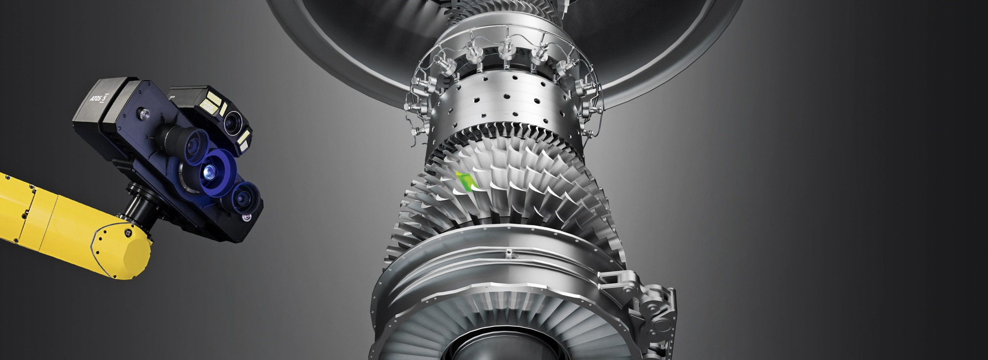
High-Speed Technology
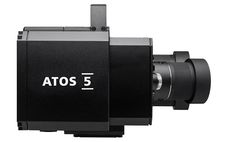
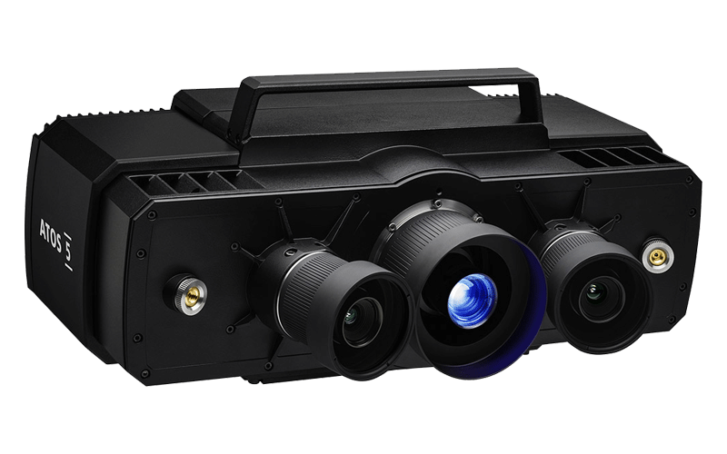
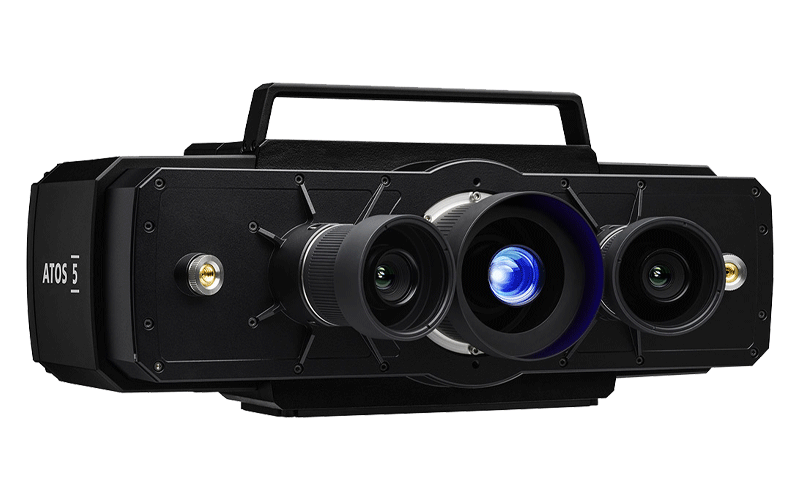
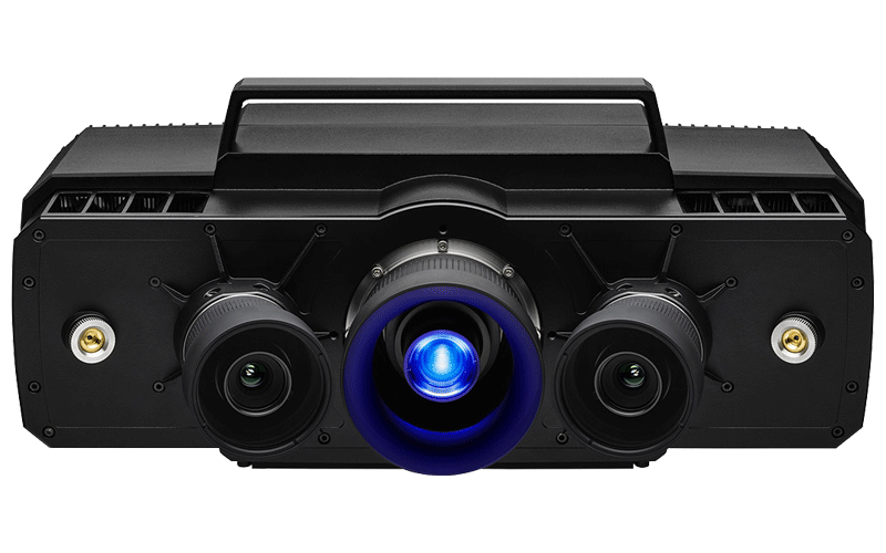
With its optimized working distance for small measuring areas and its extremely high stability ATOS 5 for Airfoil delivers high-precision data for manual and automated applications. From fan blades to turbine blades or blisks and drums to vanes (NGVs, OGVs, IGVs) and power trains: the full-field 3D measuring data allows reliable quality control, visualizing hidden errors and thus accelerate production, maintenance and repair processes.

Speed up your processes
ATOS 5 for Airfoil measures detailed quality information of new products or components from maintenance or repair at significantly reduced measuring time. The number one advantage of the ATOS 5 for Airfoil is the measurement speed. 3D scanning times of about one hour for blisks and less than 20 minutes for fan blades result from data acquisition in less than a fifth of a second.

Achieve the highest data quality
ATOS 5 for Airfoil delivers high-precision full-field data for comprehensive process and quality control of fan blades, turbine blades, blisks and different vanes (NGVs, OGVs, IGVs). The data quality provided by the sensor meets the high requirements of the industry. For the measurement of turbine blades the accuracy and thus the resolution at the edges are of particular importance.

Airfoil Inspection Features

The GOM software has a complete set of airfoil inspection functionalities. The inspection principles include standard and customizable options to meet different engineering standards and types of airfoil drawings. The user-defined inspection principle (UDIP) enables fast, standardized and efficient inspections of airfoil sections.

Surface Comparison

A 3D representation of surface deviations to the CAD or master mesh is standard in GOM technology. Surface comparisons are typically used when developing new products to search for issues in the manufacturing process. Comparisons can be made in multiple alignments including best-fit to CAD or RPS. This powerful tool reveals product details that traditional tools cannot provide.

Edge Points and Edge Circles

Edge point creation is a standard functionality and determined by the pierce point of the camber line at the leading or trailing edge with the suction and pressure side of the airfoil. Expert parameters allow moving points along the camber line. Edge circles are also automatic and generate elements at the leading or trailing edge of the airfoil.

Thicknesses

Standard functionality that creates thicknesses at the leading or trailing edge of the airfoil. The simple dialog prompts a distance value at which the thickness is to be taken from the edge point. Different options allow the measurement to be traced along the camber line. Traditional thicknesses at predefined drawing angles can also be created. A maximum airfoil thickness check is also available using the distance or maximum inscribed circle method.

Form and Position Checks

The software enables a flexible way to evaluate form and position of airfoil sections to meet end-user needs. Evaluation techniques of the actual section data can be compared using Chebyshev, Gaussian or best-fit by tolerance methods. The software can also compare the results with changing tolerance regions where tolerances are different across areas of the airfoil sections.